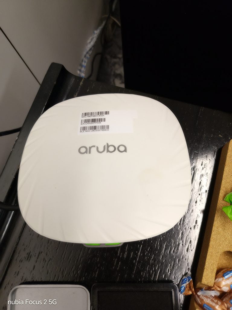
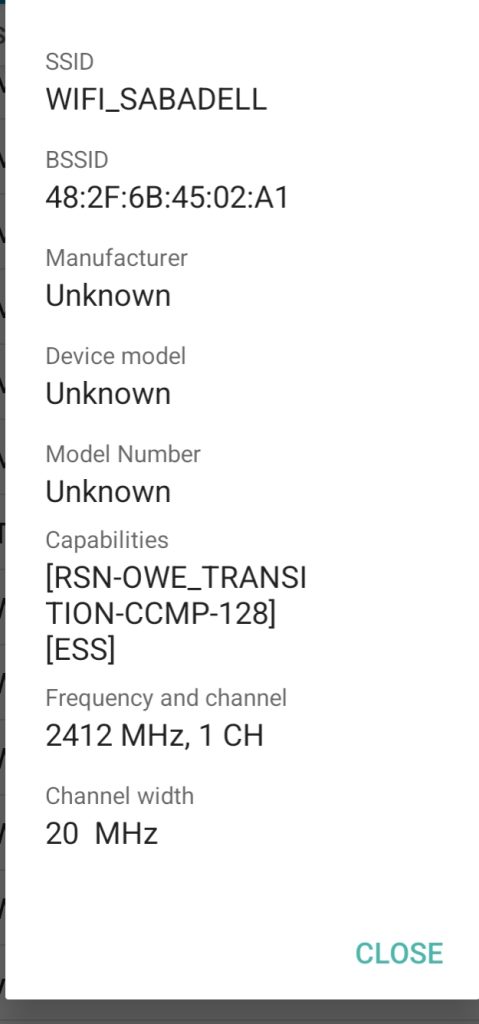
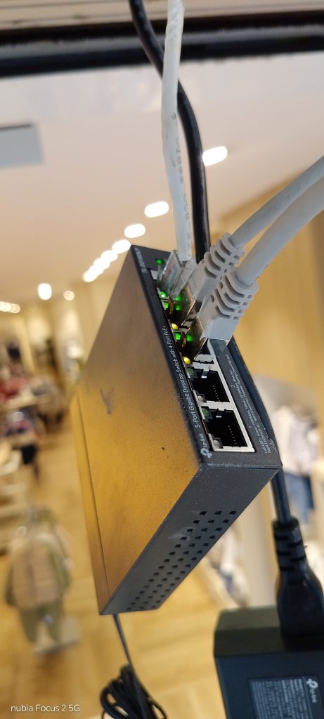
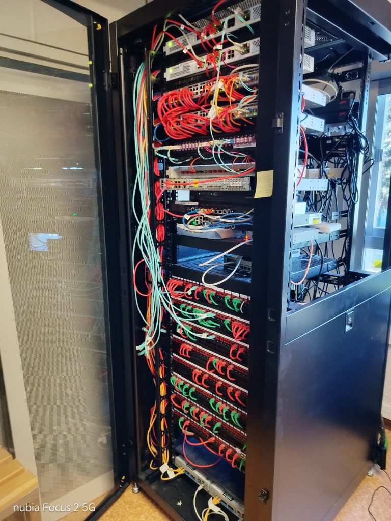
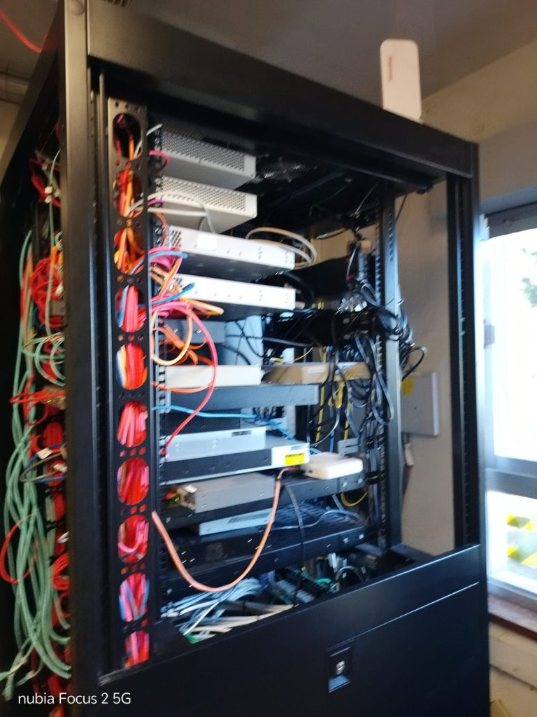
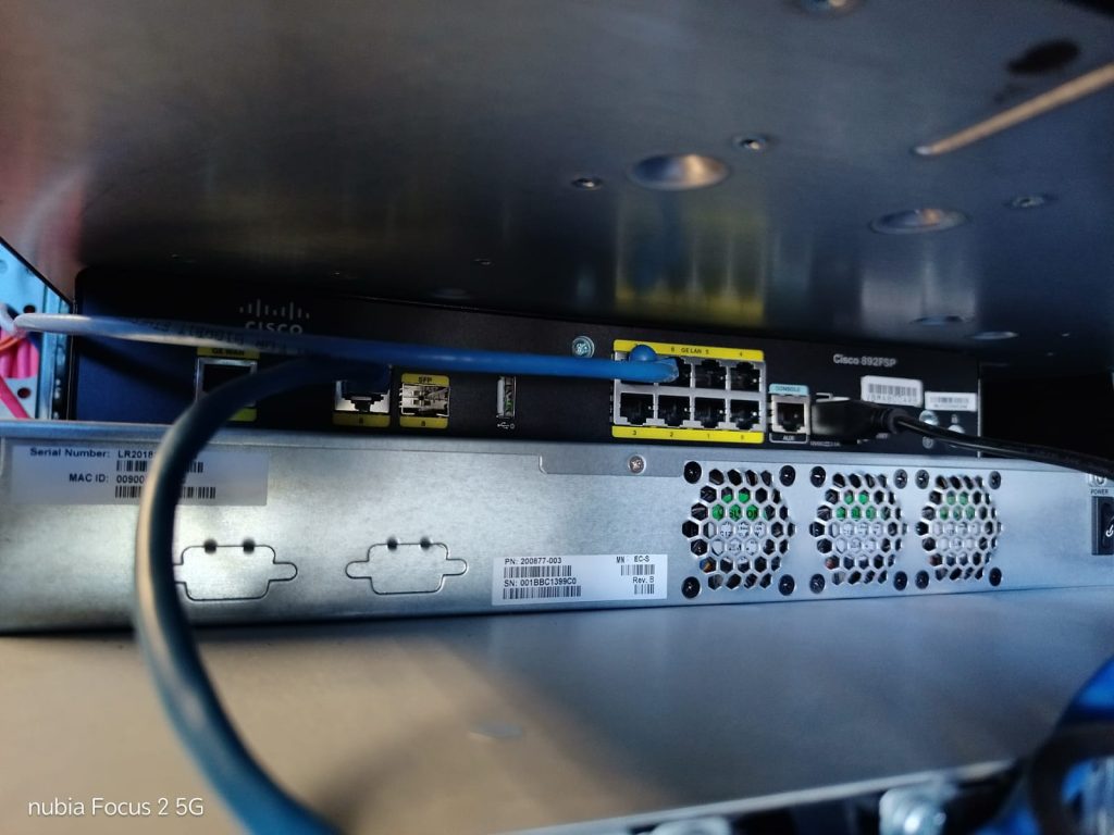
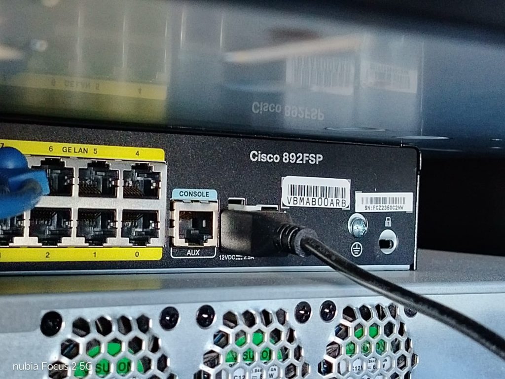
The AP (S/N CNNSKPP45) was located under a table; it failed during initial testing—specifically, it was unresponsive. I intended to swap it out, but the replacement unit also failed to show any indicator lights. I then proceeded to replace the cable and tested the AP that was already in the office; as soon as I swapped the UTP cable, it began working again. Consequently, the original office AP was kept in place, now fully operational. Tests were conducted and photos were taken; I am attaching them to this form.
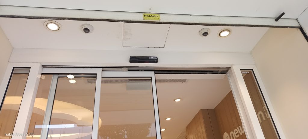
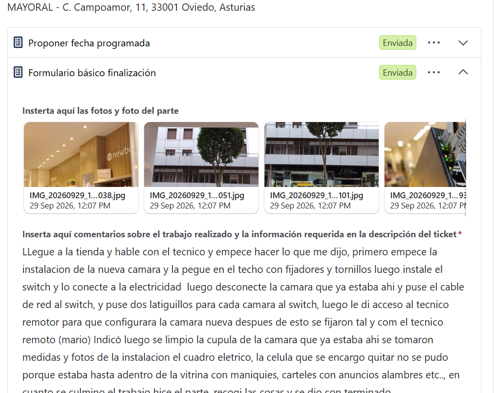
I arrived at the store, spoke with the technician, and began following his instructions. First, I started installing the new camera, mounting it to the ceiling with fasteners and screws. Next, I installed the switch and connected it to the power supply. Then, I disconnected the existing camera, connected the network cable to the switch, and ran two patch cables from the switch—one for each camera. Afterward, I granted the remote technician access to configure the new camera; once that was done, the cameras were secured exactly as the remote technician (Mario) had specified. I also cleaned the dome of the existing camera and took measurements and photos of the installation and the electrical panel. It was not possible to remove the sensor unit as requested because it was located deep inside a display case filled with mannequins, advertising signs, wiring, and other items. Once the work was finished, I completed the service report, gathered my tools and materials, and marked the job as complete.
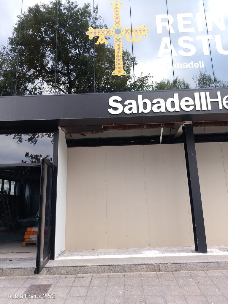
The place was under construction, so I took a look for what was need it . Materials, take measurments, photos, cable requirements, etc, I could take to long because the bank is inside of a ferialgrounds
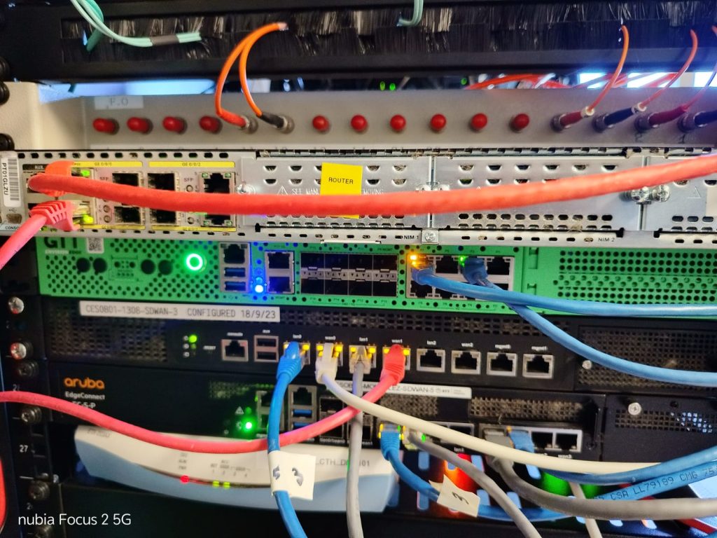
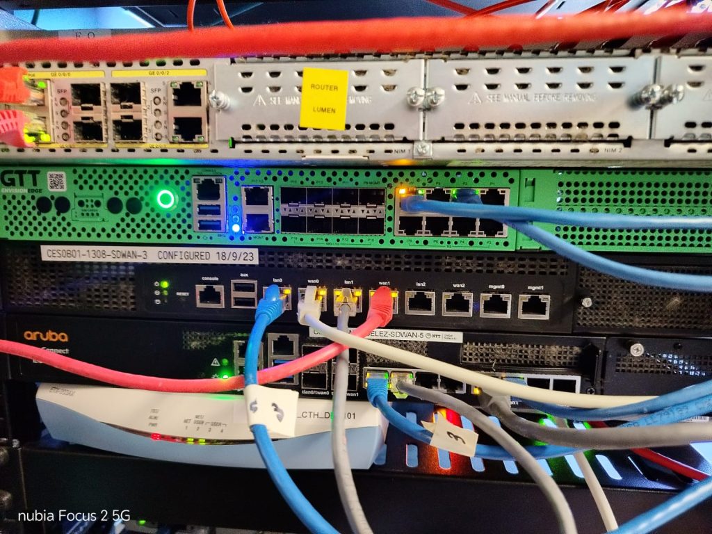
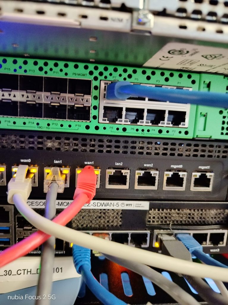
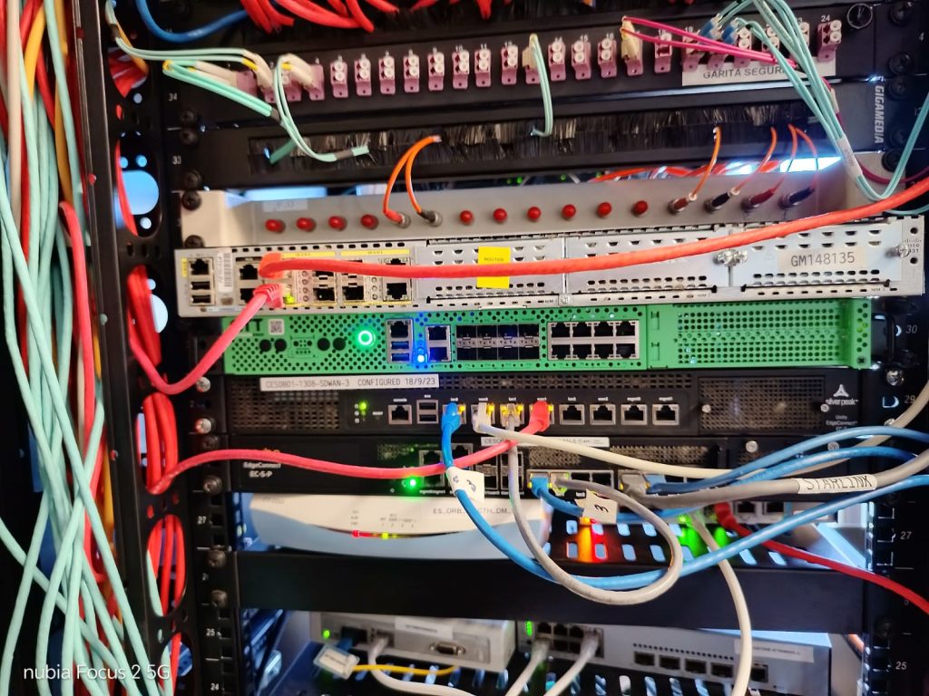
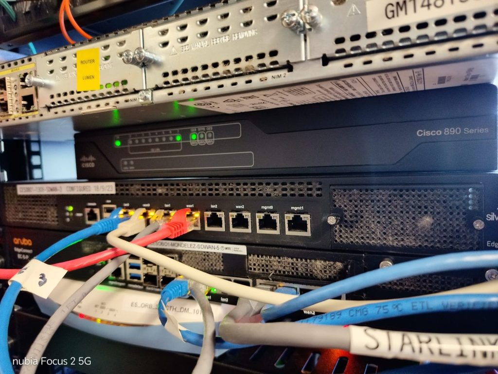
Get out the box a router devices GTT S/N 2027260163 install this device on the rack follow instrucctions from remote engineer after rack was install, I swap the WAN cable to the new router, after they make connection and configuration I swap the other cable, after this I connect to the new router and make speed test and finalize the work when they told me.
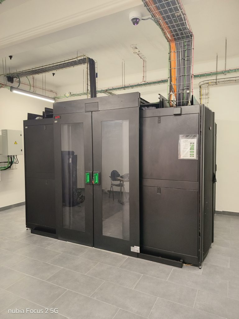
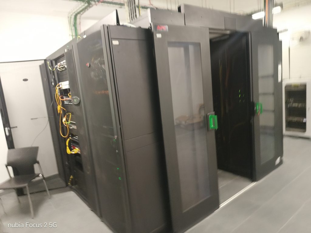
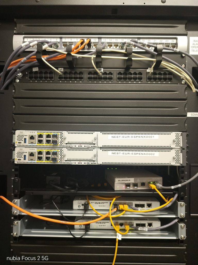
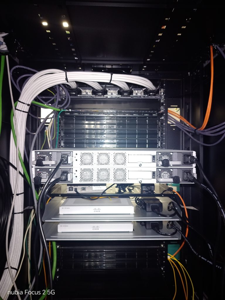
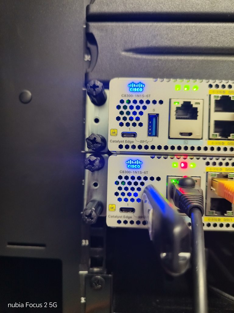
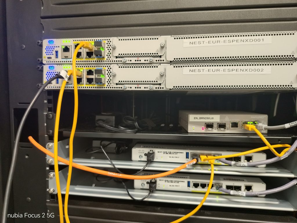
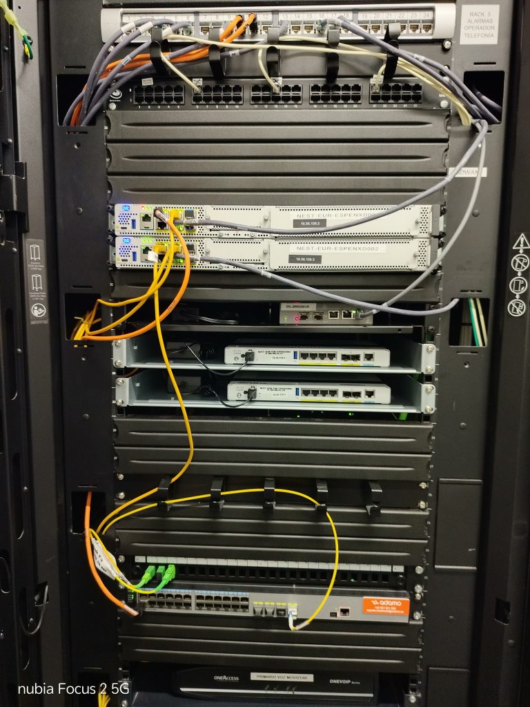
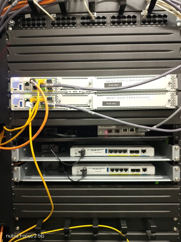
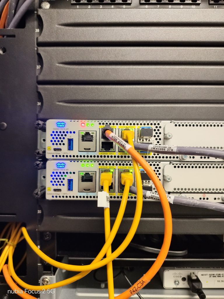
First to get to the builing was to install the two devices on the rack With bolts and tights for the power cables After this comunicate with teams with the team and the remote engineer and follow instructions. Connect secondary cisco devices c8300-1N1S-6T to the console and after share my laptop pc Screen to the group. We make an USB software update and prepare both new routers for the migration After this we made the primary and we start switching cables from old routers to new the new ones. Me make test between primary and secondary routers, and switch patch panel tag devices and complete task
It took me a long time to find the shop because the address listed was incorrect; I called the person in charge several times using the number provided here, but got no answer. Once I finally found the shop and the unit, I tried swapping the router inside the box, but it wasn’t possible because the connector was different. Since nothing else could be done, I reconnected the old unit and realized the problem was the power connector—it was defective; if you moved the cable even slightly, it would «disconnect.» I secured it with a cable tie, fastening it to another cable to hold it steady. That worked—the remote technician detected it and it was operational—but the system no longer detected the indoor sensor. I recommended replacing the old unit with a new one, but they said they weren’t authorized to do so. We agreed that the router needs to be replaced, as the new one they had sent was completely different—it lacked both antennas and a power cable.
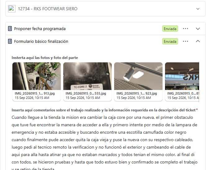
When I arrived at the store, the mission was to replace the core unit with a new one. The first hurdle was figuring out how to access it; I initially tried via the emergency light fixture but couldn’t reach it, so I kept looking until I found a camouflaged black access hatch. Once I finally gained access, I removed the old unit and installed the new one with the corresponding wiring. I then asked the remote technician to verify the setup, but the exterior components weren’t working; I had to swap cables around until I got the connections right, as they weren’t labeled and were all the same color. Eventually, I got everything connected correctly, ran tests, and—once everything was confirmed to be working properly—completed the job and left the store.
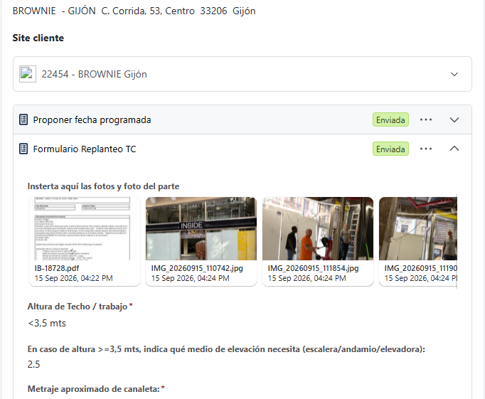
Upon arriving at the site, I realized the project was significantly behind schedule, as most of the elements needed for the layout were missing; consequently, I made rough calculations after consulting with the electrician. The electrician will install a power point for the front and another for the rear, as well as UTP cabling for an outdoor sensor on each side. Photos were taken, and the remote technician was informed.
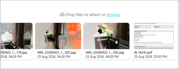
Upon arriving at the establishment, I found the sensor leaning precariously, almost falling off, as if it had been lightly bumped against the wall. I repositioned it by hand, pointing it outwards, and heard the click/people count. So I looked for a way to reinstall it on the wall. The best way was to mount it a little lower using covers and screws. I drilled, installed the covers, and secured it firmly with screws (photos attached). Everything was then ready and working.
Tras llegar al establecimiento me encuentro que el sensor esta declinado a punto de caerse como si hubiera recibido un golpe muy flojo de la pared. Lo coloco con mi mano apuntado para afuera y oigo el clickeo/conteo de Personas. Asi que busco la manera de volver a instalarlo en la pared
La mejor manera es pegarlo un poco mas abajo con fundas y tornillos, taladro y pongo las fundas y lo pego con tornillos fijamente (fotos adjuntas) y quedo todo listo y funcionando